At this point the crankshaft has been rebalanced and installed. A detailed explanation of the balancing technology will be posted soon-ish.
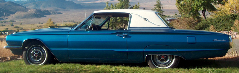
Pictures and drawings of parts of the car may leave the audience wanting to see what the finished product would look like. So I searched the internet and found a photo of a similar T-bird in the colors this project envisions.

Click to enlarge
Naturally the finished car will have <!–more–>a kick-butt stereo system. To that end I created a car-themed playlist of music that I have in my library. The selections are mostly ’80s-’90s and predominantly rhythms that could be considered a hazardous factor in excessive speed, conducive to making the acquaintance of the highway constabulary. A proper list should also include The Little Old Lady From Pasadena and other car songs by Jan & Dean, the Beach Boys’ 409. et al. Using the Comments form, feel free to suggest your own fave paeans to the Cult of the Dinosaur Burners and/or hymns to the Holy Order of the Sweet Chariot.
After installing the crankshaft, the pistons were assembled with connecting rods and rings. The rings are circular bands of metal with a diameter slightly larger than the piston. There is a gap in the ring that allows the ring to be squeezed into the cylinder, and the ring is ‘springy’ so that it always presses tightly against the cylinder wall. Each piston has three levels of rings: two compression rings and a set of oil rings. The purpose of the rings is to seal the compression chamber made by the piston within the cylinder so that a) no combustion gases leak downward out of the compression chamber and b) no oil leaks upward into the compression chamber.
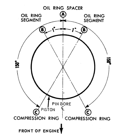
Ford ring gap illustration. (Click to enlarge)

Piston rings as installed. (Click to enlarge)
Yet even when compressed there is still a tiny gap in each ring through which leakage can occur. Therefore the ring gaps are staggered around the piston to minimize leakage. The Ford manual illustration showing gap positioning was cryptic, so I researched the topic on the web. There is much disagreement on car club web sites as to correct orientation of the rings gaps. What everyone agreed on is that the gaps in the rings should not line up vertically on the piston, allowing a direct path for leakage. The disagreement is about where on the piston the gaps should be positioned. After indecision and consideration of the competing advice, the Ford manual suddenly made sense.
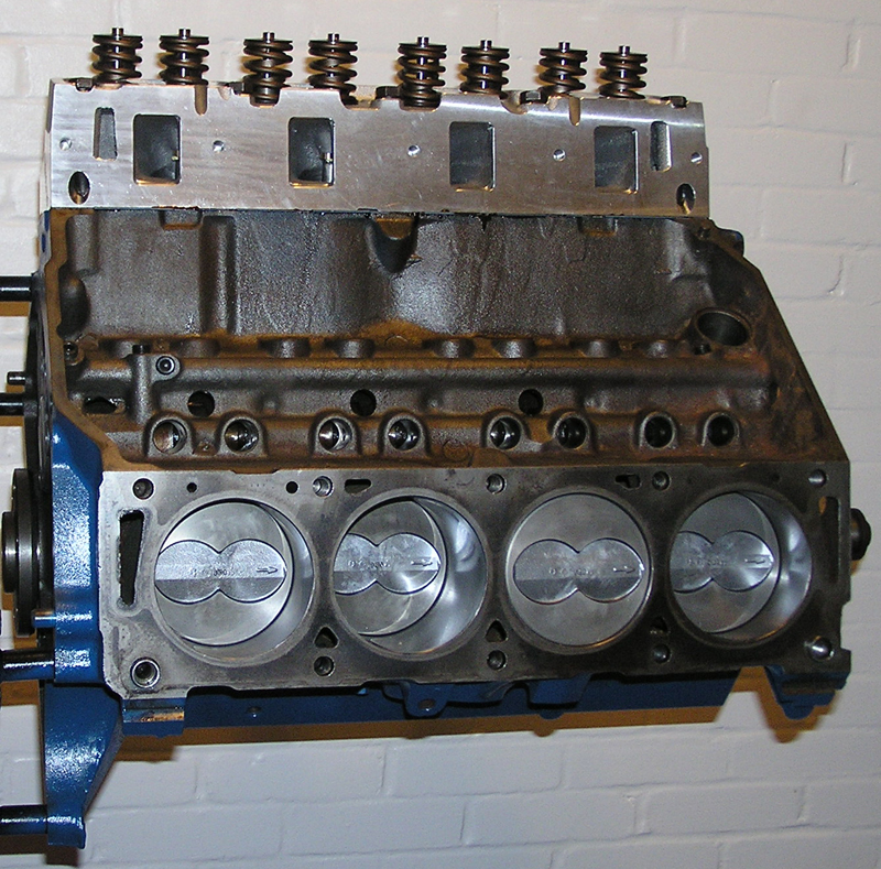
Engine block showing installed pistons and left side Edelbrock aluminum head. (Click to enlarge.)
Having sorted that out, the pistons are now installed. The new Edelbrock aluminum cylinder heads arrived and have been bolted on.