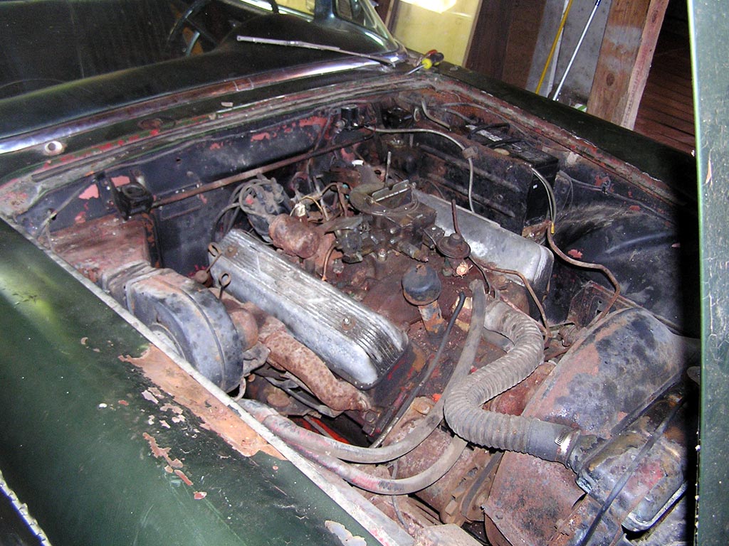
Toward the end of 2014 there were engine problems, so it was hoisted out, partially rebuilt (including a new hydraulic roller camshaft), and reinstalled. Recently it was successfully restarted.
The dog was so happy he was jumping for joy!
The new camshaft package has the advantages of modern engineering redesign and is optimized to provide more low-end power to my stock Ford 390 engine. The new camshaft package came from Competition Cams™ and includes hydraulic roller lifters. Stock hydraulic lifters contact the cam with a flat bottom surface, whereas the roller lifters contact the cam with a small rotating roller resulting in a smoother, less fricative lift.
Installing the new cam and lifters requires a detailed series of test measurements, referred to as “degreeing the cam.” Performing the tests ensures that the new cam fits properly and will operate without damage to the engine. This took a few weeks for me to complete because I didn’t fully comprehend the reasoning behind each measurement. My research was supported by the advice of, and challenges set by, my automotive mentors.
This is the order in which the measurements should be done.
1. Check the “run-out” of the installed camshaft
2. Align the crankshaft sprocket, camshaft sprocket, and timing chain for Top Dead Center (TDC).
3. Using the degree wheel, find the true TDC of the crankshaft.
4. Find the highest point (center) of the camshaft lifter lobe.
5. Establish where the cam lobe center occurs relative to TDC. Check that point against the specifications provided by the cam manufacturer.
6. Using an adjustable pushrod, measure the required pushrod length.
7. Measure to ensure sufficient clearance between the valves and pistons.
8. Purchase a set of pushrods of the measured length and install.
After reassembling the engine, it started and ran OK. But only just OK because, despite smooth idle and acceleration, there’s a tapping noise emanating from the valve covers, which is louder on the right side. I removed the valve covers to locate the source of the tapping. The oiling was good, no bent pushrods, and no valve lash. What else could it be?
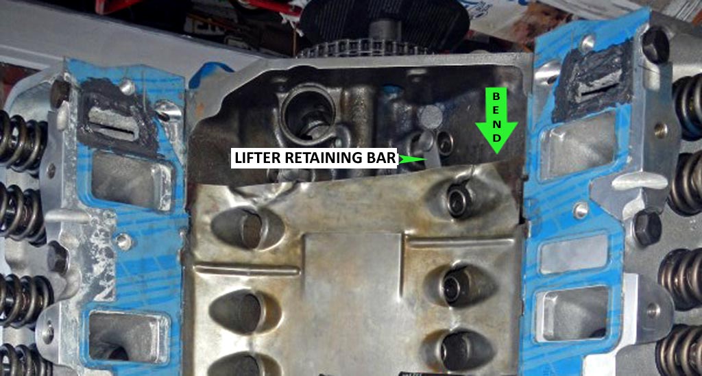
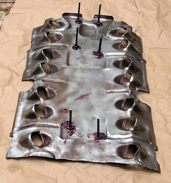
Bend in Splash Pan to Prevent Lifter Bar Tapping (click to enlarge)
I suspect the noise to be one of the roller lifter retaining bars tapping against the sheet metal splash pan that’s under the intake manifold. (I noticed that that could happen when I was degreeing the cam. Was mindful of that when I reassembled the top end, but perhaps not careful enough.) My theory is supported by a mentor at Squarebirds.com, who also had this problem. Here’s a photo of his 390 showing how to bend up the splash pan so that it clears the lifter hardware.
So once again (I’ve lost count how many times!), the intake manifold had to be removed, repairs made, engine reassembled and restarted.
Bending the baffle in the indicated spot did clear the #1 lifter bar, but then I had clearance problems at the #8 position. Truth is, the whole baffle is warped and defies attempts to bend it back to its original shape.
To ensure clearances I installed stand-offs.The stand-offs are 2″ 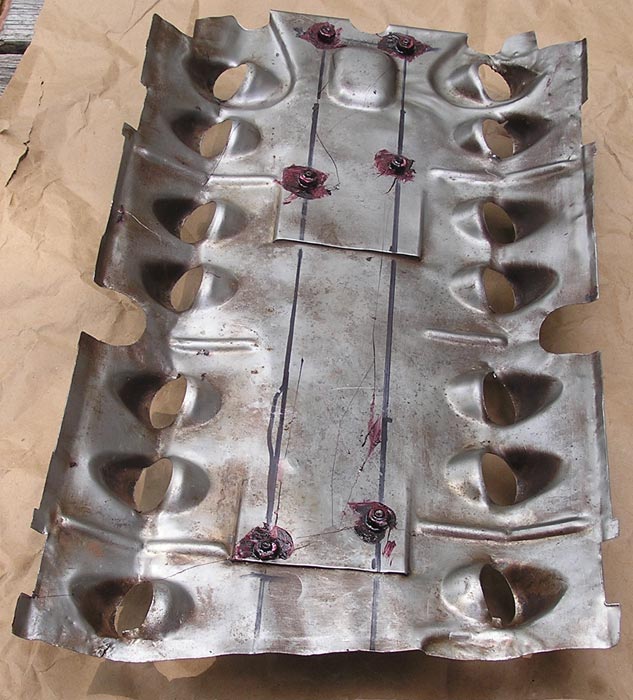 tall. Each stand-off is secured with a lock washer, opposing nuts, and sealer. The stand-offs are positioned to contact the “V” in the valley behind/between the lifter sets, so that the stand-offs stay put.
Click the photos to enlarge.
Cheers,