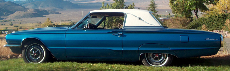
For those of you in the market for a fast classic, here’s a Ford Cobra Torino concept car in mint condition, built for speed.
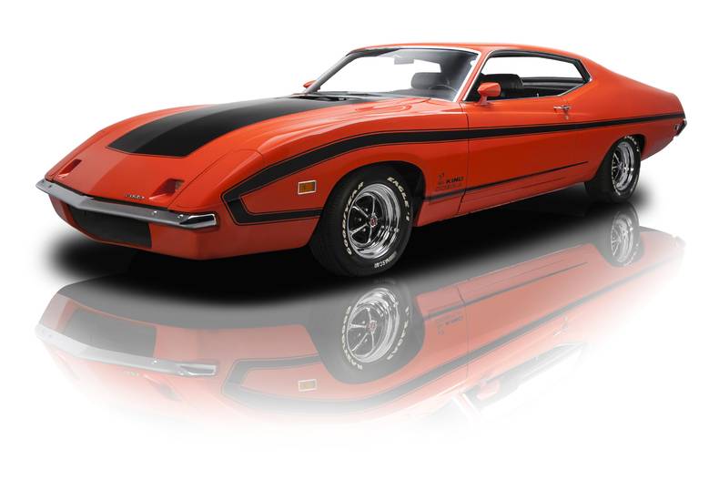
1970 Ford Cobra Torino Concept car
And it’s yours for a mere $550,000. Click this link for more views of the car.
First, the progress. Some of the hydraulic lifters were rusty, and all were generally sticky. A few of the lifters wouldn’t come apart through normal means. I discovered that by heating the lifter body with a plumbing torch, the oil inside would expand, popping the lifter piston free (actually launching them into low earth orbit: Houston, we are Go!). After getting them all apart, I cleaned them, tested them for smooth operation, and installed them in the block.
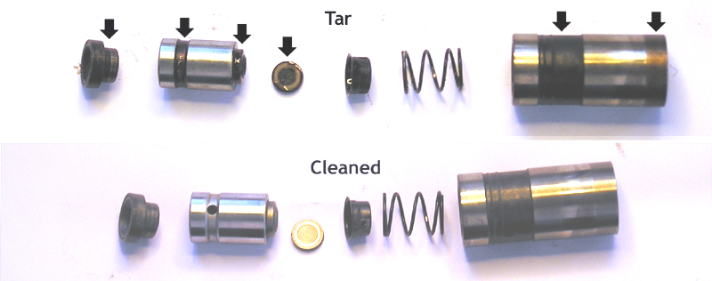
Hydraulic Lifters before and after
The other messy job was cleaning the rocker arm assemblies. The bar supporting the rockers is actually a hollow tube that transports oil to the rockers. The plugs in each end had to be removed and the gunk inside cleaned out.
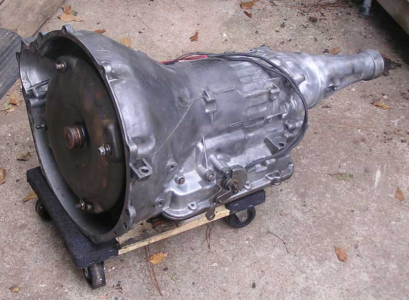
Meanwhile Scott, at Mr. Transmission (Decatur, GA; 404-921-0028), completed the overhaul of the C6 automatic transmission. Scott and his crew deserve kudos for their expertise and interest in the restoration project. Generally transmission shops have a bad reputation, but Scott has always been honest, clearly explains problems and options, and charges a reasonable amount for repairs. He also offered to delay the start of the warranty period from the time the C6 is actually installed in the car and included free operational check and adjustment of the C6 once the car is drivable. If you need transmission maintenance or repair, I highly recommend him.
The new Edelbrock aluminum cylinder heads had been bolted on (see previous post). The next step was to install the Edelbrock aluminum intake manifold. It was at this point that the project was beset by a plague of delays.
I was unable to torque the bolts securing the intake manifold to the heads. The two rear bolts wouldn’t “bite.” That is, the bolts just rotated without tightening further (and that “bites” a bear’s butt!). When I removed the bolts there were pieces of aluminum thread from the cylinder head on the bolt thread. That shouldn’t happen at the low torque applied (25 ft/lb). I had to remove the intake to inspect the bolt holes, which damaged the gaskets, which had to be replaced. (Edelbrock, are you listening?)
I called Edelbrock tech support and they suggested I use the Edelbrock bolt set. So I purchased a set: in fact there is no difference between the length or thread of the Edelbrock bolts and the bolts I was using. I grant that the Edelbrock bolts are prettier. After three more calls to tech support, they agreed to send me a few heli-coil inserts to repair the bolt holes in the head. As well as a customer satisfaction issue, I fault Edelbrock for not showing an acute investigative interest in what may be a quality control problem in their manufacturing process.
Given the circumstances, I reckoned it prudent, long term, to insert heli-coils in all ten bolt hole locations. No doubt this jeopardizes the warranty, but what other reasonable option? With trepidation and much angst, I carefully drilled into my $1600 set of Edelbrock heads and tapped the threads for the inserts. As it turned out, the retrofit was successful and the heads and intake manifold will shortly be reassembled onto the block.
The aforementioned process occurred over a period of several weeks, so in the interims I began rebuilding the 4-barrel Holley carburetor. The carb is one of the most complicated devices on the car. It operates on principles of pressure differential, Bernoulli’s law, and the Venturi effect. Complexity withstanding, overhauling the carb is simply a matter of taking it apart, cleaning out the carbon build-ups, using the air compressor to blow out all the fuel/air/vacuum passages, and re-assembling it with new parts and gaskets.
I ordered the rebuild kit from Daytona Parts. By mistake, the first kit that they sent was for a 2-barrel carb. The Daytona folks were very kind, and sent me the correct kit plus a paid return envelope to send back the 2-barrel kit. However, near the end of the rebuild I discovered that one of the gaskets in the new kit was the wrong size. Knowing this would be difficult to explain over the phone, I scanned the gasket image into my CAD software, added dimensions showing the discrepancy, and emailed it to Daytona. They concurred with my observation – turns out they’d sent a variant version of my 4-barrel kit. Again, they were very apologetic and express shipped a new, correct kit. Happily, despite the minor delays, none of these iterations cost a dime more than the original price.
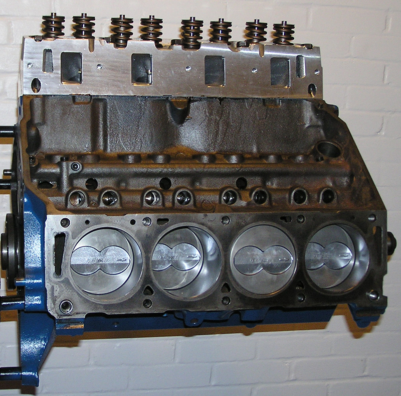
Remaining tasks of the engine reassembly are:
- insert lifter rods
- attach timing chain cover and harmonic balancer
- bolt on water pump
- insert distributor assembly
- bolt on exhaust manifolds
- flywheel
- mate engine with C6 transmission
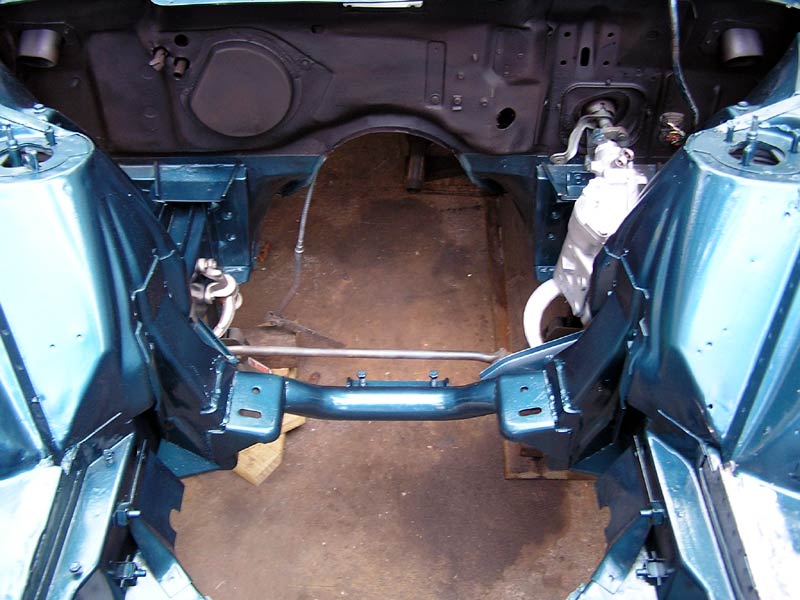
To prevent possible damage to carburetor, alternator, power steering pump, and fan, they’ll be attached after engine installation. In parallel to engine reassembly, the car itself has been worked on in preparation for receiving the engine. The engine bay was rewired; the dashboard and associated engine controls have to be renovated and reinstalled; cooling system readied; the exhaust system is being worked on; brake system overhauled; etc.
So stay tuned — the fun just never ends!
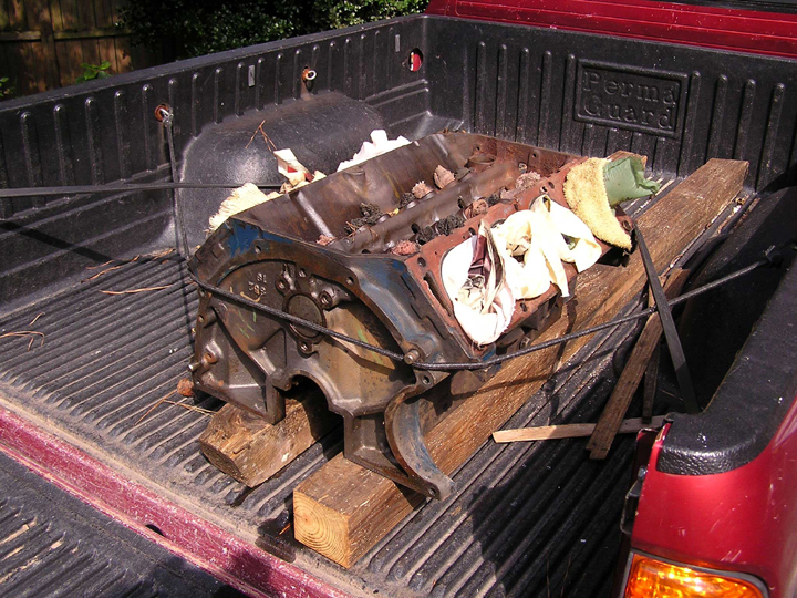
![The [mostly] reassembled engine, ready for installation (click to enlarge)](http://www.hwythunder.com/wp-content/uploads/2014/04/engineRe-aasy.jpg)