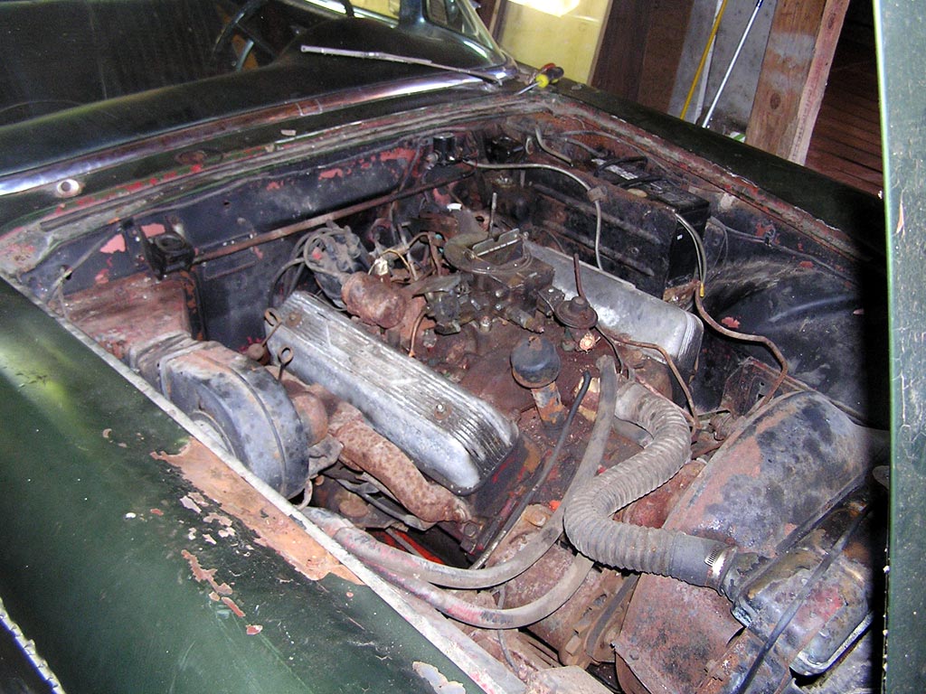
My 390 FE has a hot camshaft and a Street Demon 4-barrel carb. It’s been trouble tuning it to optimum. It’d be running fine and then, for no apparent reason, stall. Restarting afterward often problematic. The car wasn’t being driven enough because I had no confidence that it wouldn’t leave me stranded on the road far from home. Had always thought that this was due to my inexperience in doing a proper tune-up. So I took the car to a shop specializing in performance engines and had them do the tune up.
When I picked the car up it ran better than it ever had before. It drove fine through the surface streets leading to the highway and then ran OK at highway speeds. But after about 10 miles, off the highway in stop-n-go traffic, it stalled again. It would restart but stall when put in gear. After several start-stall iterations, it died completely. Had to tow it home. The next day I got it started (using some canned starting fluid) and was able to drive it a short distance.
Started it again a few days later. After a full warm up, it idled smoothly for about 5 minutes and then faltered and died. It was beginning to dawn on me that the problem was more than what a tune-up could remedy.
Suspecting a possible problem with the stock mechanical fuel pump, I compared the specs for the Demon carb and the stock fuel pump. The input fuel pressure range for the carb was slightly higher than the output range of the pump, although the nominal numbers did fall within both ranges. However, the pump was old (the original). So I decided to install an electric fuel pump.
The carburetor manufacturer suggested the Mr. Gasket Model 12S as meeting their pressure and flow specs. The new fuel pump solved the problem of erratic engine behavior and sudden stalling. Here are some pictures of the installation. (Click each to enlarge.)
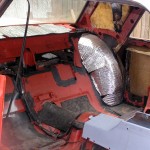
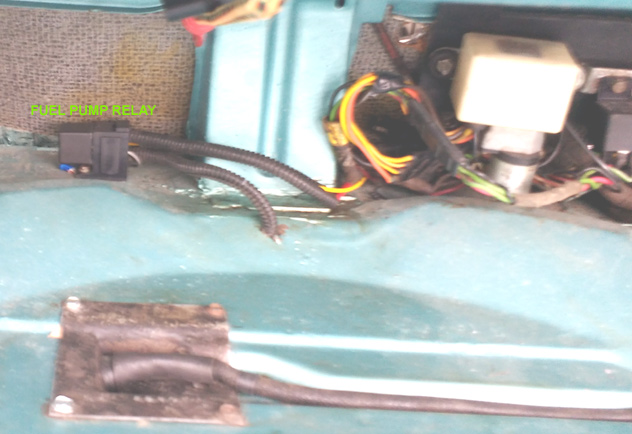 Fuel Pump Relay in Trunk. Wiring to battery and fuse box is routed through center console. |
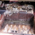
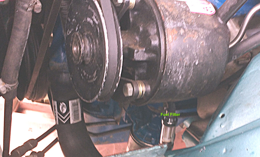 Secondary Fuel Filter. Primary fuel filter is mounted to Fuel Pump. |
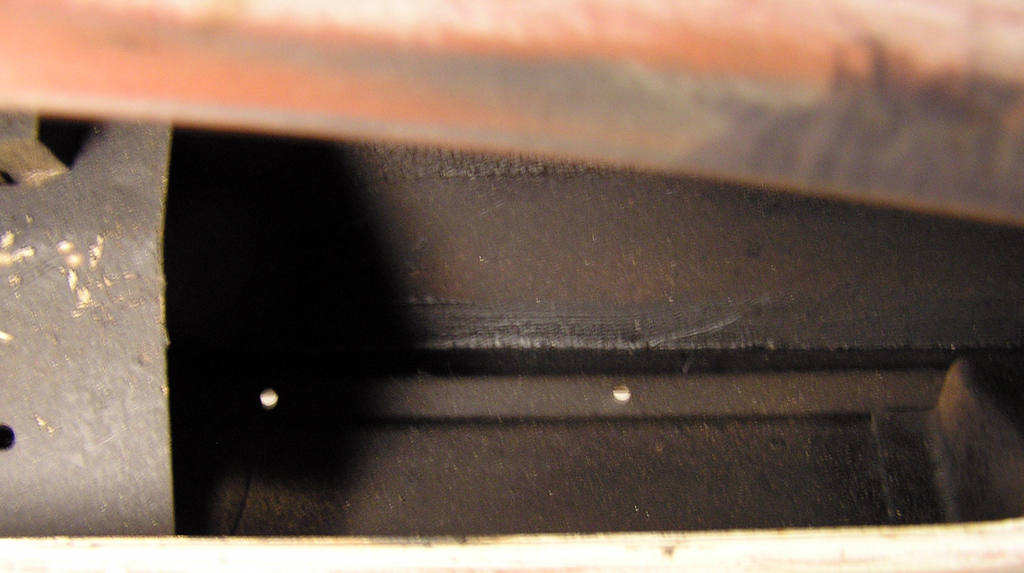
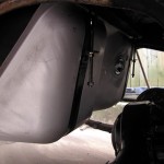
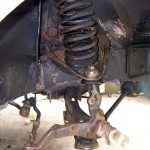
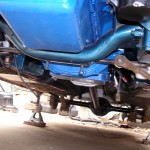
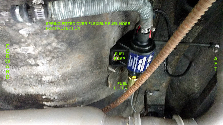 Fuel pump mounted under car forward of fuel tank in rear axle well. Flexible hose is protected from road damage by routing it through a steel spring. |
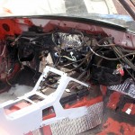
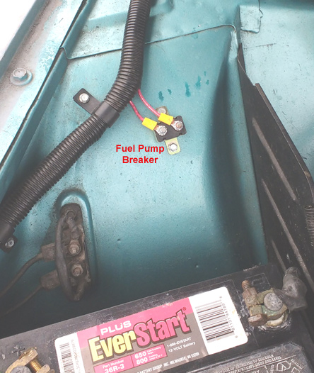 Circuit breaker for fuel pump, connected to battery + at starter relay. |